Table of Contents
Sherline CNC Training SOP
Last edited: Furst (08/26/20)
Overview:
- This training provides an introduction to using and operating the Sherline CNC glass drill including:
- Safety
- Applications
- Software
- File types
- Flashcut
- Sample prep
- CNC Setup
- G-code Modification
- Drilling
- Printer Maintenance
- Changing Print Heads
- Changing Fulfillment Type
- Cleaning
- Remember to enter job information into the 3D print job log!

Safety
Eye injuries can result from flying chips or broken bits. Cuts can occur from contacting sharp tools or broken glass. Burns can result from hot cutting tools or parts. Serious injury can result from pinching or entanglement in moving parts. Poor housekeeping creates tripping and cutting hazards for other users. Do not leave machine running unattended. Eye protection, closed toe shoes, long pants, and protective clothing must be worn when using this machine to prevent injury. Long hair must be tied back and jewelry must be removed before operating this machine to prevent entanglement.
Applications
The Sherline CNC is used exclusively for for drilling holes in glass, ceramic, silicon, and other brittle materials. Milling of brittle materials is not supported. The Sherline uses a high speed spindle in combination with abrasive diamond drill bits to slowly abrade the material away.
Typical applications include adding macro to micro interface connecters to Microfluidics chips.
Software
The Sherline CNC uses a retrofit Sherline mini mill in combination with the FlashCut CNC software. This SOP does not cover dxf2fgc conversion code.
FlashCut CNC offers a user interface for positioning, zeroing, and running the G-code, however it has no CAM capabilities. This means that G-code must be hand written based on the location of holes.
Sample Prep
A backing plate is required for drilling, and should be bonded to the substrate to be drilled to improve backside cut quality and prevent drilling into the fixture. If bonding is not permitted, slowing down cut speed may result in less blowout on the backside of the hole and a backing plate should still be used.
- set CrystalBond hotplate to 121 degrees C
- place a sheet of tinfoil or wax paper over hotplate to avoid spilling of crystal bond
- place sample and backing plate on covered hot plate and allow them to reach equilibrium
- using the CrystleBond stick and a pair of tweezers to hold the sample in place, gently paint on a thin layer of Crystal Bond to both the substrate and backing plate
- using tweezers, flip the substrate over and place CrystalBond sides together, wiggle side to side to minimize air bubbles.
- place the hot bonded slides on the teflon fixture and align the substrate and backing plate. Remove from heat.
- After sample has cooled, use a razor blade to remove any CrystalBond on the edges of the sample. This will insure that edge finding finds the edge of the sample, rather than the edge of the crystlebond.
- After drilling is done, place back on hotplate to separate backing plate from sample before placing sample in acetone to remove any remaining CrystalBond.
CNC Setup

- Turn on the Flashcut CNC box
- On the Sherline computer, start FlashCut CNC (thunderbolt icon)
- Within FlashCut, select the home tab, followed by seek home. This will move all axis to their zero position.
- load the edge finder into the drill chuck
- select the jog menu from the FlashCut software
- using the faster setting, jog the edge finder to just below the edge of the fixture and within a quarter inch of the top left corner edge in both X and Y.
- start the spindle by slowly ramping up the speed from zero (starting the spindle at full speed can result in damage to the motor) to between 800 and 1300 RPM.
- switching to incremental jog, slowly jog in x or y until the edge finder kicks out
- once kicked out, zero the program axis and repeat for the other axis
- turn the spindle off and jog the spindle up and away from the fixture
- offset the X, Y program coordinates to account for the radius of the edge finder
- offsetting by the radius can be easily accomplished by keying in values to the program coordinate system.
- zero the program coordinates again, and verify the center of the edge finder is directly over the corner of the fixture
The machine is now zeroed in X and Y
- clamp the bonded sample into the top left corner of the fixture
- Without changing the coordinates, swap the edge finder for the selected abrasive drill bit that you intend to drill with
- Using the jog commands, position the spindle over a sacrificial portion of the sample
- slowly ramp the spindle speed up to full speed and apply diluted Kool Mist coolant over the sample and within the fixture.
- using incremental jog on slow speed, slowly bring down the bit until it enters the fluid and just touches the surface of the wafer. a small plume of glass dust will be seen when the rotating bit contacts the wafer or glass surface.
- zero the program Z axis.
- raise the spindle using the jog function and turn off the spindle.
The machine is now zeroed in X, Y, Z
G-code modification
The sample G-code is as follows:
G21 (select mm units) G49 G80 G90 (cancel offsets, cancel cycles, absolute coordinates) G98 (Move the drill away from the part when drilling is finished)
G00 X0 Y0 Z5 (rapid move to the upper left corner of slide, 5mm above)
(Hole drilling blocks)
(G73=canned peck drilling cycle 1) G73 X17 Y-12.5 z-1.2 Q.1 R0.5 F2.5 (x=coordinate of hole, y=coordinate of hole, Z=depth of hole, R=retract value, Q=depth of each peck, F=feedrate)
(G73=canned peck drilling cycle 2) G73 X58 Y-12.5 z-1.2 Q.1 R0.5 F2 (x=coordinate of hole, y=coordinate of hole, Z=depth of hole, R=retract value, Q=depth of each peck, F=feedrate)
(Closing block) M30
When using G73 canned cycle, X and Y set the coordinates of the hole, and Z sets the maximum depth below machine zero. R sets the starting height of the drilling cycle as well as the retract height between pecks) (Q sets the depth each peck will go into the workpiece until it excedes the Z value set above. F sets the feedrate or the rate at which the drill will decend into the workpiece) (If you are cracking the slide or getting excessive break out you should reduce the feedrate value and the depth of each peck.
The Z value should be slightly deeper than the thickness of the sample without backing plate. This insures all holes drilled in the sample are through holes. NEVER drill without a backing plate as you will hit the fixture.
Drilling
- load the program within FlashCut by selecting file in the upper right hand corner, followed by open G-code
- the file should be visible in the bottom left hand corner of the FlashCut GUI. ensure all values are correct before continuing
- cover the slide and the fixture with coolant; the drill will be ruined if it runs dry
- ramp up the spindle to max speed
- select the start button to run the G-code
- as the machine drills, flush the cut continuously with coolant to wash away glass particles and chips
- use the vacuum line to soak up any extra coolant during the run
Rates
- hourly billing for lab use applies
- No additional charges result from tool time
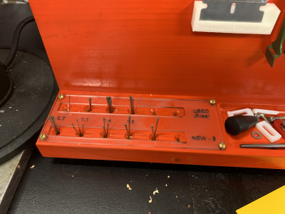
- Used drill bits are free
- If a new dill bit is selected, ensure it is logged within FBS so recharge can be applied