
Table of Contents
CNSI Innovation Workshop and Microfluidics Lab Battery Segment Manufacturing Safe Operating Procedures
Last Updated: 5/6/23 Jason
This SOP provides a guide to safely manufacture and assemble battery segments of the GR23 electrical vehicle. Some of the information is compiled from the following sources.
Safety Considerations
- Electrical shock & arc flash
- Short Circuits
- Electrical Insulating PPE
- Electrical Insulating Tools
- Clear workspace of non-insulated tools
Location
Battery assembly should take place on one of the workbenches in the Innovation Workshop in Elings 2442.
Safety and Materials section applies to both the Trotec and Rayjet Laser Cutter
Overview
- Safety considerations, how they can occur, and how to avoid electrical accidents
- Battery segment drawing and pictures
- Machining of insulation panels
Safety Considerations
This laser engraving system contains a class 4 carbon dioxide (CO2) laser that emits intensive and invisible laser radiation. Without safety precautions the direct radiation or even diffuse reflected radiation is dangerous!
- Always wear safety glasses when using the machine.
- Always work with the machine cover closed.
- NEVER leave the laser machine alone when running a job. If you do need to leave,
- The machine door must be left open while you are away.
- Do not store any flammable materials in the inside of the device or in the immediate vicinity of the device.
- Remove leftovers of previously produced materials before running a job.
- A fire extinguisher/fire blanket must always be handy as the laser beam can ignite flammable materials.
- Metals, particularly un-coated aluminum, copper, silver and gold, cannot be processed with the laser and lead to high reflections of the laser beam. If needed, metals can be coated with a paint/tape which chemically bonds to the surface when engraved.
- Before processing materials the user must verify whether harmful materials can be generated and whether the filter equipment of the exhaust system is suitable for the harmful materials.
- PVC (polyvinyl chloride) must under no circumstances be processed with the laser.
- Looking directly into the laser can cause retinal damage.
- Confirm that the fume collection system is running whenever the laser is cutting or engraving.
Material
Always check materials list BEFORE attempting to cut/engrave a material. If unsure contact IW Staff.
Allowed Materials
Plastics:
- ABS (acrylonitrile butadiene styrene)
- Acrylic (also known as Plexiglas, Lucite, PMMA)
- Delrin (POM, acetal) — for a supplier, try www.mcmaster.com.
- Kapton tape (Polyimide)
- Mylar (polyester)
- Nylon (melts badly)
- PDMS
- PETG (polyethylene terephthalate glycol)
- Polypropylene (PP) — melts somewhat
- Styrene
- Two-tone acrylic — top color different than core material
Foam:
- Depron foam (often used for RC planes)
- EPM
- Gator foam (foam core gets burned and eaten away compared to the top and bottom hard shell)
Other:
- Cloths (leather, suede, felt, hemp, cotton)
- Magnetic Sheets
- Papers
- Rubbers(neoprene, etc supplier try: mcmaster.com)
- Woods(MDF, balsa, birch, poplar, red oak, cherry, holly, etc. supplier try: midwestproducts.com)
Prohibited Material
- Metals (our laser cutters are not powerful enough nor setup to cut through metals and attempting to do so could damage the machine)
- Metals (cannot be engraved however a certain type of paint/tape which chemically bonds with the metal may be used to mark materials)
- Polycarbonate (PC, Lexan) — Lexan creates large amounts of fumes
- Teflon (PTFE, Polytetrafluoroethylene) – cutting creates Fluorine gas
- Any material containing chlorine
- PVC (Cintra) — contains chlorine
- Vinyl — contains chlorine
- HDPE: “milk bottle” plastic. It gets gooey, melts and catches on fire.
- Epoxy
- Glass — you can engrave glass, but trying to cut it will cause cracking or breakage
- Fiberglass
- Printed circuit board (FR4 and other material types)
- Carbon Fiber
Mounting Materials in the Bed
Each printer has a honeycomb bed that is good for general laser cutting and engraving. The honeycomb bed is meant to support the part without damaging the bed underneath by the laser; the honeycomb bed should be used when making through cuts. If needed, parts may be mounted on the bed using magnets
Cutting with the Trotec Laser Cutter
- Turn the printer on with the power switch in the left back corner. Allow the printer to initialize, the bed will go to the bottom position.
- Place material on bed. Larger parts should be placed over the honeycomb bed but, if your part is too small, you can lower the bed, remove the honeycomb barrier, and secure a piece of acrylic to the bed with magnets to place your part on top of.
- Focus printer on material by using the focusing tool. Place the focusing tool on the edge of the laser head and raise the bed until the tool either touches the material or falls off.
- If cutting very thick material(>1/4in) focus offset may be needed so that the laser is focused in the center of the material
- Open CorelDraw and upload your .DXF or .PDF file using the folder icon in the top left corner. Alternatively, you can use CorelDRAW to outline your cut.
- Set the size of the drawing to the size of the bed: 24” x 11.99”.
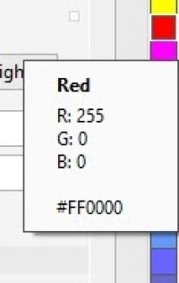
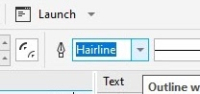
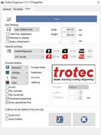
- Features being cut should be in RGB Red and set to “hairline” thickness. Features being engraved should be RGB Black. When dragging a color over from the right hand menu, a solid-colored box will indicate that the entire shape will be filled with that color and a colored square outline means that only the outline of the shape will be colored.
- Select print and click on the print setting button.
- Choose the correct material properties from the menus
- New material recipes can be created in Job Control
- Make sure that “minimize to jobsize” and “cut inner geometries first” are selected.
- Click the JC (job control) button.
- Make sure that “Print to file” and “Single file” are selected and then click print. Save your file to the desktop.
- Job Control will now open. Ignore any “empty” error messages. Drag your file from the jobs menu on the right hand side to the preview plate on the left. Connect to the printer by clicking the USB icon.
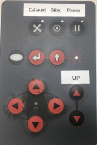
- Position the laser on your material where the upper land corner of your cut will be by using the directional arrows on the machine.
- The crosshairs in Job Control indicate the position of the laser on the bed. Make sure the zoom is set to “Fit to plate”. Drag the icon of your drawing in the preview plate so that the upper left corner is at the crosshairs.
- Double check material properties and that the recipe is correct
- If you want to use Nitrogen instead of air for the air assist, turn both valves on the right back of the printer to Nitrogen. Make sure you turn off the Nitrogen regulator valve after each print as to not waste Nitrogen.
- You can outline your job on your material with the laser pointer before you make your cut by right-clicking the icon of your drawing in the preview plate.
- If everything is OK, click the play button and your part will begin to print.
- YOU MUST NOT LEAVE WHILE PART IS BEING CUT AS FIRES COULD OCCUR
- Once the print has been completed, open the lid, lower the bed and remove the part. Make sure all pieces of material are removed from bed.
- Turn off the printer and close the lid. The computer should be left on.


Troubleshooting the Trotec Printer
- If JobControl will not allow you to drag your file onto the build plate, either “minimize to job size'' were not checked, or your build plate dimensions are bigger than those of the Trotec bed size
- Double check that your drawing is 24” x 11.99” in CorelDRAW
- In Job Control, go to the “plate” dropdown menu, “plate setup”, and make sure the plate is set to 24” x 11.99” and “fit to plate” is selected.
- Make sure that cuts are hairline thickness.
- If the PC will not connect to JobControl after clicking the USB button try restarting JobControl or turning the printer off and back on after 5 sec.
- If the jobs menu disappears from the right side of Job Control, you can get it back under the “view” dropdown.
Cutting with the Rayjet Laser Cutter
- Turn the printer on with the power switch in the left back corner. Allow the printer to initialize, the bed will go to the bottom position.
- Place material on bed and raise the bed using the up and down arrow keys.
- Focus cutter on material by using the focusing tool. Place the focusing tool on the edge of the laser head and raise the bed until the tool either touches the material or falls off.
- If cutting very thick material(>1/4in) focus offset may need to be added so that the laser is focused in the center of the material
- Open your part in CorelDraw and ensure lines being cut are set to hairline thickness and are RGB red(select line and right click on red in color selection panel to the far right)
- Features being engraved must be RGB Black
- Position part on the page where it will be cut in the printer. (precise instructions for printing in the correct location are below)
- Click Print and click the print settings button. The Rayjet Control Manager will open.
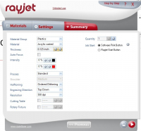
- Click on the summary tab and ensure Material Group, material and thickness are correct
- Make sure autofocus is off and take note of Job Start method
- If it is in ”software print button” mode, print will start immediately after print has been clicked in CorelDraw while “Hardware print button” mode will only start after job has been started in Rayjet MiniManager.
- Ensure all settings are correct and click the play button. You will return to CorelDraw
- Click print in CorelDraw
- Open MiniManager by opening it on desktop and then right clicking on icon in bottom left of screen and clicking “MiniManager”
- Ensure all settings are correct and click start when ready to begin print.
- YOU MUST NOT LEAVE WHILE PART IS PRINTING AS FIRES COULD OCCUR
- To do the same job multiple times, right click on the job and select “reset job”
- Once the print has been completed, open the lid, lower the bed and remove the part. Make sure all pieces of material are removed from bed.
- Turn off the printer and close the lid. Computer should be left on.

Positioning where the part will be printed on the Print Bed; Rayjet printer only
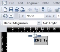
- Move Laser head to where you want the top left corner of your print to be.
- Open MiniManager and choose the Laser tab to see the coordinates of the laser head.
- In CorelDraw ensure that the page dimensions are set to 28.556in by 17.010in. This will ensure the print is in the correct location on the bed.
- In CorelDraw input the x coordinate as it is shown in the Laser tab
- Input the y coordinate as 17 minus the y coordinate shown in the Laser (this is due to CorelDraw and the printer having opposite y axes)
- Make sure the coordinate origin for your object is set to the upper left corner.
- Your print is now located so that the top left corner will be where the laser head is on the bed.
Troubleshooting the Rayjet Printer
The Rayjet printer and printer software is much more confusing and less intuitive than the Trotec Printer. If one of these issues occurs when attempting to print, try these things.
- Rayjet MiniManager won’t open due to “another instance of MiniManager is already open”
- Make sure that Rayjet MiniManger is not open on another user in the computer or in the background
- Try right clicking and selecting open in the Windows task bar
- Try force closing it with the Task Manager
- Try Restarting the computer
- You click print in CorelDraw but the print is not added to the queue in MiniManger/the print does not begin.
- This happens when jammed files are left in the MiniManager queue. Delete all files from the queue in MiniManager by clicking delete.
General Material Recipes For Acrylic
| Thickness | Engraving Settings | Cutting Settings |
|---|---|---|
| 1/16“ | 50% power, 25% speed | 100% power, .6% speed |
| 1/8” | 50% power, 30% speed | 100% power, .45% speed |
| 1/4“ | 50% power, 30% speed | 100% power, .2% speed |
General Curf Width For Acrylic
| Thickness | Curf Width |
|---|---|
| 1/16” | .001“ |
| 1/8” | .0065“ |
| 3/16” | .085“ |
| 1/4” | .0056“ |
| Thickness | Engraving Settings | Cutting Settings |
|---|---|---|
| 1/16” | 40% power, 100% speed | 100% power, 5.0% speed |
| 1/8“ | 40% power, 100% speed | 70% power (65% if acrylic does not have protective cover), 0.8% speed |
| 1/4” | 40% power, 100% speed | 100% power, 0.5% speed |
| 1/2“ | 40% power, 100% speed | 100% power, 0.3% speed |
Creating New Material Recipes
To create a recipe for a new approved material, begin by doing research on what power and speed is generally used for your material. Be sure to account for the differences in speed and power of the printer you’re using versus the printer which you found the material recipe for. Your recipe will be a Speed(0-100%) and Power(0-100%) setting for both engraving and cutting your material. Cutting will need significantly more power/less speed than engraving. Remember that a lower speed will result in a higher cutting intensity and vice versa. To make a new recipe, click the setting menu in JobControl select Material settings. Create a new recipe for each color indicating whether it is cutting or engraving. Many recipes are already available for use/reference in JobControl. Creating a new recipe for a material will require experimentation of different power and speed values. Always start conservatively so as not to cause a fire or damage the printer. Slowly move up in intensity(higher power, lower speed) until you reach the intended cutting intensity. For example, if the laser is not fully cutting through the material, either increase power or decrease speed. If part is overly burning/melting, decrease power or increase speed.
Printer Maintenance
Lens and Mirror Cleaning Printer Lens and Mirrors must be cleaned weekly to remove the buildup of dirt and dust and prolong the life of the lens and mirror. There are two mirrors however mirror #2 requires removing the right side maintenance panel and should only be cleaned by IW staff. Always check Lens cleaning log before printing and ensure the lens was cleaned at least 2 weeks before. To clean the lens and Mirror #1:
- Ensure Laser cutter is off
- Wearing Nitrile gloves, remove the lens from the head with cloth/bubble wrap underneath incase lens is dropped.
- Blow off any dust from lens with compressed air
- Wipe lens once with lens cleaning solution and lens wipes found in the Laser cutter bin
- Put a drop of lens cleaning solution on lens and let sit for a minute before wiping off
- Repeat with other side of lens
- Replace the lens in the correct orientation with concave side pointing up.
- Remove the mirror using the set screws and clean in the same fashion as the lens. Replace mirror
- Log the cleaning of the lens and any additional notes such as condition of the lens in the lens cleaning log
Particulate Filter Change for Atmos Compact
- Turn off the Atmos and unplug the main.
- Open the filter housing, the black drawer will be seen on the left.
- Unplug the measurement hose (connected to the front of the drawer) and carefully pull the drawer out of the housing.
- Unscrew the front of the drawer, this area is the activated carbon housing.
- Remove the activated carbon and the filter mats (located on the sides) into a disposable bag.
- Place the new mats in, noting that the blue imprints should face the exterior of the drawer.
- Pour in a limited amount of activated carbon. If the mats stay in position, proceed to fill the container with activated carbon.
- Close the chamber with the fasteners.
- Slide the drawer back into the filter housing. Make sure that the filter is sitting firmly and is attached airtight to the back of the housing.
- To reset the error signal, press “+” and ”-” on the control panel consecutively for 3 seconds. The LED should then read “Activated Carbon OK.”
Note the following when conducting maintenance on the Atmos:
- All waste from the compact must be labeled as hazardous before disposal.
- A more detailed list of all the error commands on the exhaust system can be found on page 40 of the manual (linked at the beginning of the SOP).
Laser Cutter Quick Review
Tool Lead:
Contact: andrewfurst@ucsb.edu
Safety Concern
- Looking directly into the laser can cause retinal damage.
- Do not cut unapproved martial including PVC, Metal, HDPE, compost materials containing epoxy, anything whose composition includes Chlorine or Florine.
- Do not leave laser cutter running untended for any reason
- Do not lift acrylic cover shield when laser is running
- Nitrogen back fill on mFL lab should be used when cutting materials prone to igniting.
- Confirm that the fume collection system is running whenever the laser is cutting or engraving.
- Laser lenses must be cleaned within ONE WEEK of time of use. If lenses has not been cleaned, clean before use to avoid damaging lenses.
Safe Operating Procedures Review
- Turn on laser cutter and fume extractor
- Use focusing tool to set bed height based on workpiece, move laser to desired starting position
- Launch CorelDraw and import 2D sketch as PDF or DXF. Take the time to check scale using built in page rulers
- Set lines to be cut as RED and patterns to be engraved as BLACK. (must use true RGB red and black)
- Select Print → Print settings
- Within Print settings select desired laser recipe based on material and thickness, verify one click print is turned off, print order is set to inner features first, and import dimensions from CorelDraw is selected
- Click Print
- Navigate to Trotec software
- Check Scale, do a dry run without laser power if necessary
- Send job to laser cutter
Maintenance
- Mirror and lens mounted on cutting head should be cleaned once a week or before starting a job
- In body mirror (mirror #2) should be cleaned by Innovations Workshop staff once a month
- Acrylic top should be cleaned (inside and out) with Fantastik cleaner once a week DO NOT USE IPA
- Particulate filter for fume extraction should be cleaned and replaced as needed