
sae_battery_segment_manufacture_assembly
This is an old revision of the document!
Table of Contents
CNSI Innovation Workshop and Microfluidics Lab Battery Segment Manufacturing Safe Operating Procedures
Last Updated: 5/6/23 Jason
This SOP provides a guide to safely manufacture and assemble battery segments of the GR23 electrical vehicle. Some of the information is compiled from the following sources.
Location
Battery assembly should take place on one of the workbenches in the Innovation Workshop in Elings 2442.
Overview
- Safety considerations, how they can occur, and how to avoid electrical accidents
- Battery segment design
- Necessary materials, tools, and equipment
- Machining of insulation panels
- Assembly of Enepaq modules within insulation
- Wiring voltage taps, thermistor connectors, and other connections
- Sealing up battery segment and finishing assembly
Safety Considerations
- Electrical shock & arc flash
- There are two primary ways that direct current electrical injury can occur:
- Body completing the loop in a high voltage circuit (touching positive and negative terminals of a high potential battery segment)
- Non-insulated tool or a conductive material completes the circuit in a medium to high voltage circuit, generating an explosive arc that can produce intense heat
- Electrical Insulating PPE
- Referencing this Electrical Insulating PPE Guide, working with electric potentials between 50-750VDC (GR23 battery segment is 110V max voltage, entire battery pack is 546V max voltage) requires:
- class 00 gloves
- nonconductive safety glasses
- insulated tools
- long sleeve shirt & pants
- closed toed shoes
- Since the max voltage that we are working with is 110V max, an insulating mat and EH rated shoes are not necessary
- Workspace
- As mentioned above, ensure that no non-insulated tools can fall across battery terminals or be accidentally used
- No machining of metals should occur while battery segment terminals are exposed
Battery Segment Design
…
Necessary Materials, Tools, and Equipment
Each printer has a honeycomb bed that is good for general laser cutting and engraving. The honeycomb bed is meant to support the part without damaging the bed underneath by the laser; the honeycomb bed should be used when making through cuts. If needed, parts may be mounted on the bed using magnets
Cutting with the Trotec Laser Cutter
- Turn the printer on with the power switch in the left back corner. Allow the printer to initialize, the bed will go to the bottom position.
- Place material on bed. Larger parts should be placed over the honeycomb bed but, if your part is too small, you can lower the bed, remove the honeycomb barrier, and secure a piece of acrylic to the bed with magnets to place your part on top of.
- Focus printer on material by using the focusing tool. Place the focusing tool on the edge of the laser head and raise the bed until the tool either touches the material or falls off.
- If cutting very thick material(>1/4in) focus offset may be needed so that the laser is focused in the center of the material
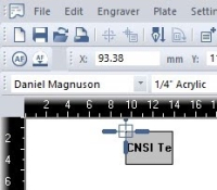
- Open CorelDraw and upload your .DXF or .PDF file using the folder icon in the top left corner. Alternatively, you can use CorelDRAW to outline your cut.
- Set the size of the drawing to the size of the bed: 24” x 11.99”.
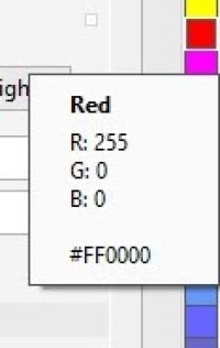
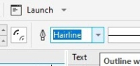
- Features being cut should be in RGB Red and set to “hairline” thickness. Features being engraved should be RGB Black. When dragging a color over from the right hand menu, a solid-colored box will indicate that the entire shape will be filled with that color and a colored square outline means that only the outline of the shape will be colored.
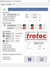
- Select print and click on the print setting button.
- Choose the correct material properties from the menus
- New material recipes can be created in Job Control
- Make sure that “minimize to jobsize” and “cut inner geometries first” are selected.
- Click the JC (job control) button.
- Make sure that “Print to file” and “Single file” are selected and then click print. Save your file to the desktop.
- Job Control will now open. Ignore any “empty” error messages. Drag your file from the jobs menu on the right hand side to the preview plate on the left. Connect to the printer by clicking the USB icon.
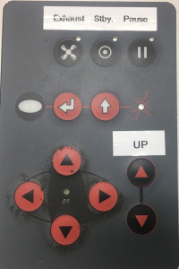
- Position the laser on your material where the upper land corner of your cut will be by using the directional arrows on the machine.
- The crosshairs in Job Control indicate the position of the laser on the bed. Make sure the zoom is set to “Fit to plate”. Drag the icon of your drawing in the preview plate so that the upper left corner is at the crosshairs.
- Double check material properties and that the recipe is correct
- If you want to use Nitrogen instead of air for the air assist, turn both valves on the right back of the printer to Nitrogen. Make sure you turn off the Nitrogen regulator valve after each print as to not waste Nitrogen.
- You can outline your job on your material with the laser pointer before you make your cut by right-clicking the icon of your drawing in the preview plate.
- If everything is OK, click the play button and your part will begin to print.
- YOU MUST NOT LEAVE WHILE PART IS BEING CUT AS FIRES COULD OCCUR
- Once the print has been completed, open the lid, lower the bed and remove the part. Make sure all pieces of material are removed from bed.
- Turn off the printer and close the lid. The computer should be left on.


Troubleshooting the Trotec Printer
- If JobControl will not allow you to drag your file onto the build plate, either “minimize to job size'' were not checked, or your build plate dimensions are bigger than those of the Trotec bed size
- Double check that your drawing is 24” x 11.99” in CorelDRAW
- In Job Control, go to the “plate” dropdown menu, “plate setup”, and make sure the plate is set to 24” x 11.99” and “fit to plate” is selected.
- Make sure that cuts are hairline thickness.
- If the PC will not connect to JobControl after clicking the USB button try restarting JobControl or turning the printer off and back on after 5 sec.
- If the jobs menu disappears from the right side of Job Control, you can get it back under the “view” dropdown.
sae_battery_segment_manufacture_assembly.1683443609.txt.gz · Last modified: 2023/05/07 07:13 by wei