
This is an old revision of the document!
Table of Contents
Carbide 3D Training SOP
Last edited: Furst (09/08/20)
Instructor:
Date:
| Name | Group or Company | Signature | |
|---|---|---|---|
| 1 | |||
| 2 | |||
| 3 | |||
| 4 | |||
| 5 | |||
| 6 |
Overview:
- This training provides an introduction to using and operating the Carbide 3D Desktop CNC including:
- Software
- Carbide Motion
- Carbide Create
- Solidworks
- HSM Works
- File Types
- G-Code
- .EGC
- Choosing tools and related feeds/speeds
- Setting up a job
- Machine Limitations
- Machine Maintenance
Safety
- Safety Glasses must be worn when machine is running
- The acrylic shield must be in place and lowered before starting a job
- The spindle must be completely stopped before adjusting or removing work piece
- After milling is completed, the work piece will have developed sharp burrs which must be removed with a hand file or sandpaper
Software
CAD:
Carbide 3D makes a rudimentary design software called Carbide Create which can be used to create basic designs; however, Solidworks offers a much more robust features set do create complex and easily modifiable 3D models. This SOP assumes a base knowledge of Solidworks and assumes the user has taken ME-12S or has comparable machining knowledge.
CAM:
Once the design is complete the Carbide Motion can be used to create the toolpaths, however this SOP will use HSM Works due to its integration with Solidworks and more complex feature set. HSM Works is installed on any Innovations Workshop computer running Solidworks 2020 including the Ultimaker and Carbide 3D computers. many toolpaths will likely be necessary to create the CAM nessesary to machine the part. To generate the toolpaths:
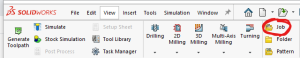
- Select the CAM window from within the Solidworks Command Window (note that CAM is an HSM Works plug in and is different from Solidworks CAM and Solidworks CAM TBM and will not appear unless HSM Works is installed on the computer) \\
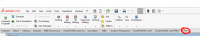
- The Command Window will now show HSM Works functions
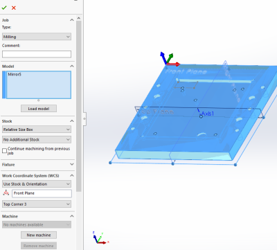
- Select “New Job” to specify desired part to machine, define size of raw stock, and indicate the part zero and work holding coordinate system.
- Typically the back left corner is used for part zero as shown
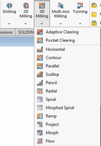
- Select the first desired machining operation from the 2D or 3D machining drop down
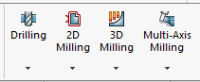
- The 2D machining drop down is used for many 2D operations including slotting, facing, pocketing, and chamfering
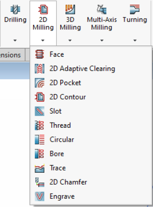
- The 3D operations can do 2D machining operations such as adaptive pocket clearing, however it is typically used for adaptive clearing or machining requiring all 3 axis simultaneously
- 2D and 3D operations require many of the same input perimeters including
- Tool and cutting rate
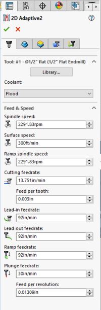
- Tools can be selected from the “all” category of the tool library based on desired tool and modified using the edit button if necessary to set number of flutes and sickout /geometry of tool and tool holder
- Selecting a tool automatically generates generic feeds and speeds for a much more ridged machining center. Feeds and speeds should be set based on the provided chart under references
- Desired machining geometry
- Simply select the desired face or feature to machine in the current operation.Toggling off Z propagation and tangent propagation can be used to select smaller or partial features.
- If this operation is finishing machining a feature based on the previous operation check “rest machining” and input the second tools diameter
- Cutting/retract heights
- Typically selecting machining geometry will set many of the heights automatically, however they can all be altered if necessary
- Machining passes


- Part of feeds and speeds, HSM Works will auto fill many of the boxes, however due to the limited power and rigidity of the machine, stepdowns should be reduced based on the reference material and “multiple passes” should be used to reduce cutter load
- “Material to leave” can be adjusted to create roughing passes if desired. Many operations such as adaptive clearing will automatically leave stock as it is assumed to be roughing operations.
- Linking
- Linking moves dictate how the cutter enters and exits the workpiece and can be altered to prevent the cutter from running into the stock while it attempts to start or finish a cut cleanly.
- Posting
- Post the code by selecting Post Process and selecting Carbide 3D (grbl) as the post configuration. The program name or number should be numbers only, and is typically notated 00001 (not necessary for carbide but good practice for larger machines) make sure to select the desired output folder as by default Solidworks buries the G-code
Job Setup
- At the Computer::
- Load your STL file into the print software on the computer adjacent to the printer (Cura for Ultimaker, GrabCad Print for F270).
- Set Print Parameters:
- Position the part on the build tray in a way that is conducive to 3D printing (flat side down)
- Select appropriate layer or slice height (the more slices the higher the print resolution but the longer it takes to print)
- For Ultimaker:
- Select “generate support” if necessary
- Check appropriate filament and bed temperatures (should be set if using standard filament load out)
- Send job to Ultimaker using USB drive
- For F270:
- The F270 the printer will print a raft before printing the model. Make sure first layer is set to support material or removal will be incredibly difficult.
- Send job to F270 over Ethernet
- Record the material used and print time in the online log along with the other job information requested. The print log should be on the desktop or https://docs.google.com/forms/d/e/1FAIpQLScS3URUxoHOR62PdQeeSTAYg_suV061UsoFafrgoN0qn6DWYg/viewform.
- At the printer:
- Ultimaker:
- Make sure print bed is clean
- F270:
- Make sure that there is enough room on an CLEAN build tray for your part, and that the build tray is secured in the printer with the locking arm horizontal. Build trays may be used until the entire build area has been printed on, but printed areas should ideally not be reused.
- Start the job at the printer
Part Removal and Cleaning
Ultimaker
- Remove part from print bed using a spatula or razor being careful not to cut yourself or scratch the build plate. Make sure no body part is in line with the tool should it slip or the part break free unexpectedly.
- If support was used, submerge print in warm water for several hours to dissolve PVA filament. (prints can warp if submerged in water for over 24 hours)
F270
- Don gloves, face shield, and lab coat
- Carefully, slowly and without splashing cleaning solution open the support removal tank lid, remove and open the tank
- Place large parts directly in the tank, small parts may be put in the SS box and placed into the main basket.
- Carefully, slowly and without splashing lower the basket back into the tank and close the lid.
- Set timer for 6 hours setting the temperature to 80 degrees C.
- After cleaning time has elapsed follow the instructions above for opening and removing parts.
- Rinse part in warm water
Rates
F270:
| Material | $/Spool | cu in/Spool | $/cu in | $/cc |
|---|---|---|---|---|
| PLA | 79 | 60 | 1.31 | .08 |
| ABS | 164 | 60 | 2.73 | .17 |
| Sup | 228 | 60 | 3.79 | .23 |
F270 hourly charge: $1/hr to pay for head replacement
Ultimaker: ABS: .12/gram
Ultimaker 3 Quick Review
Tool Lead: Andrew Furst
Contact: Andrewfurst@ucsb.edu
Safety Concerns
- Both print heads and bed are heated during operation. Do not attempt to clean, remove, or adjust without allowing for adequate cool down time.
- Keep hands clear of printer during operation. Pause print before clearing or adjusting print.
Safe Operating Procedures Review
- Launch Cura version 4 (blue icon)
- From connected printers, select IW-Ultimaker3
- Select File → Open Files → Open desired project (.STL file type)
- Using task bar on the left hand side, position model as desired
- From print settings, select slice height, infill percentage, and support
- Support can be generated using ether nozzle, typically nozzle one holds build material with nozzle two printing with dissolvable support material.
- Setting can be fined tuned using the “Custom” option from print settings
- Within custom settings, nozzle and build plate temps can be adjusted (build plate temps should be based off of build material)
- Save the file from Cura on a thumb drive
- Connect thumb drive to printer → select desired file → select print
Note: Adjusting settings may lead to more (OR LESS) successful prints. Contact Workshop Wizard responsible for Ultimaker if print fails or knowledge of advanced settings is desired.
Post Processing
- If support was constructed from ABS carefully break away with pliers
- If support was constructed from PVA soak part in warm water for several hours to dissolve support structure
Maintenance
- Bed should be cleaned with IPA between prints
- Print heads and silicone head protector should be cleaned as needed
- Filament should be dried before use if printer has been idle for several weeks
- Bed leveling should be completed every time print cores are swapped
- Print cores should be swapped or purged after clog or to change print line width. Used print heads should be kept for spare parts