
millsop
Table of Contents
Manual Milling Machine Training SOP
Last edited: Furst (10/12/20)
Instructor:
Date:
| Name (Last, First) | Group or Company | Signature (First, Last) | |
|---|---|---|---|
| 1 | |||
| 2 | |||
| 3 | |||
| 4 | |||
| 5 | |||
| 6 |
Tool Location
Innovation Workshop, Elings 2448
Overview:
PM-25MV Mill
- A 3-axis mill with R8 spindle. Spindle speeds varies continuously from 50-2500 rpm.
- Weight: 275 lbs
- Spindle motor: Brushless DC 750 W (1 HP)
- Travel
- X-axis: 20.5”
- Y-axis: 7”
- Z-axis: 13”
- Axis locks
- Quill lock
- 4” Vice
- Hold downs for vice
- Indicating vice
- DRO
- One for table and headstock. A separate DRO for quill.
- Functions
- Zeroing
- Inputting coordinate
- Metric/inch interchange
- Absolute/incremental coordinates
- Automatic half
- Calculator
- Entering tool offset
Training
Safety Hazards
- This machine is designed for milling and drilling operations by experienced users familiar with metal-working hazards.
- Wear ANSI-approved full-face or eye protection at all times when using the machine (everyday eyeglasses are not reliable protection against flying particles).
- Wear proper apparel and non-slip footwear – be sure to prevent hair, clothing or jewelry from becoming entangled in moving parts. Gloves – including tight-fitting disposables can be hazardous!
- Be sure the work area is properly lit.
- Never leave chuck keys, wrenches or other loose tools on the machine.
- Be sure the work piece and machine ways are secure before commencing milling or drilling hold-downs and/or vise fully tightened, X-Y-Z axes locked, cutting tool secured
- Use moderation: light cuts, low spindle speeds and slow table motion give better, safer results than “hogging”.
- Don’t try to stop a moving spindle by hand – allow it to stop on its own.
- Disconnect 110V power from the mill before maintenance operations such as oiling or adjustments
- Maintain the machine with care – check lubrication and adjustments daily before use.
- Clean the machine routinely – remove chips by brush or vacuum, not compressed air (which can force debris into the ways).
Setup
- Turn on the mill
- Turn on DRO by flipping switch on back
- Turn on Quill DRO by pressing power button
- Once part and tool are secure, spindle may be turned on by pressing the green power button on the speed controller panel
- Setting up a vice
- Install the T-bolts and align the vise by eye. With one of the clamp nuts snug, but not tight, tighten the other one just short of fully-tight (but tight enough so the vise won’t budge without a definite tap from a dead-blow mallet).
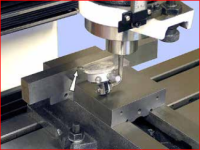
- Adjust the Y-axis to pre-load the indicator to mid range at the tightly-clamped side of the vise, then lock the Y-axis. Do not allow the spindle to rotate during this procedure.
- Note the indicator reading, then watch the indicator as you traverse the table slowly toward the loosely clamped side. (Also watch for any sign of spindle rotation.) Ideally, there should be no discrepancy between the indicator readings at the two ends — unlikely at the first attempt. Return the table to the starting point, then repeat the process, tapping the vise in as you go. Repeat the process as often as necessary for the desired accuracy, progressively tightening the “looser” nut. Now fully tighten both nuts, and re-check again (tightening a nut can itself introduce significant error).

Change Tooling
- Remove Tooling
- Lock the spindle with the C-wrench, loosen the drawbar one half turn or less, just enough to unseat the taper, then tap the top of the drawbar with a soft hammer to release the R-8 device. Unscrew the drawbar with one hand while supporting the R-8 device with the other hand.
Install Tooling
- Install the R-8 device, then hand-thread the drawbar into it until the shoulder on the drawbar bottoms on the splined spindle, diagram above (on the machine this is concealed by the drawbar cap, Figure 3-2). Lock the spindle with the special C-wrench, page 5, while at the same fully tightening the drawbar with an 8 mm wrench.
Securing the part
millsop.txt · Last modified: 2021/04/27 17:39 by furst