
Table of Contents
Carbide 3D Training SOP
Last edited: Furst (09/08/20)
Instructor:
Date:
| Name | Group or Company | Signature | |
|---|---|---|---|
| 1 | |||
| 2 | |||
| 3 | |||
| 4 | |||
| 5 | |||
| 6 |
Overview:
- This training provides an introduction to using and operating the Carbide 3D Desktop CNC including:
- Software
- Carbide Motion
- Carbide Create
- Solidworks
- HSM Works
- File Types
- G-Code
- .EGC
- Choosing tools and related feeds/speeds
- Setting up a job
- Machine Limitations
- Machine Maintenance
Safety
- Safety Glasses must be worn when machine is running
- The acrylic shield must be in place and lowered before starting a job
- The spindle must be completely stopped before adjusting or removing work piece
- After milling is completed, the work piece will have developed sharp burrs which must be removed with a hand file or sandpaper
Software
CAD:
Carbide 3D makes a rudimentary design software called Carbide Create which can be used to create basic designs; however, Solidworks offers a much more robust features set do create complex and easily modifiable 3D models. This SOP assumes a base knowledge of Solidworks and assumes the user has taken ME-12S or has comparable machining knowledge.
CAM:
Once the design is complete Carbide Create can be used to create the toolpaths, however this SOP will use HSM Works due to its integration with Solidworks and more complex feature set. HSM Works is installed on any Innovations Workshop computer running Solidworks 2020 including the Ultimaker and Carbide 3D computers. many toolpaths will likely be necessary to create the CAM nessesary to machine the part. To generate the toolpaths:
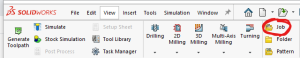
- Select the CAM window from within the Solidworks Command Window (note that CAM is an HSM Works plug in and is different from Solidworks CAM and Solidworks CAM TBM and will not appear unless HSM Works is installed on the computer) \\

- The Command Window will now show HSM Works functions
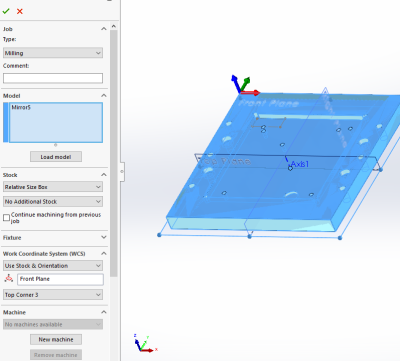
- Select “New Job” to specify desired part to machine, define size of raw stock, and indicate the part zero and work holding coordinate system.
- Typically the back left corner is used for part zero as shown
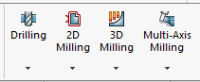
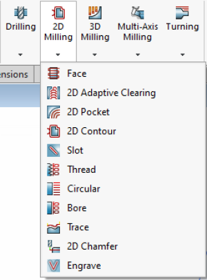
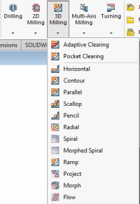
- Select the first desired machining operation from the 2D or 3D machining drop down
- The 2D machining drop down is used for many 2D operations including slotting, facing, pocketing, and chamfering
- The 3D operations can do 2D machining operations such as adaptive pocket clearing, however it is typically used for adaptive clearing or machining requiring all 3 axis simultaneously
- 2D and 3D operations require many of the same input perimeters including
- Tool and cutting rate
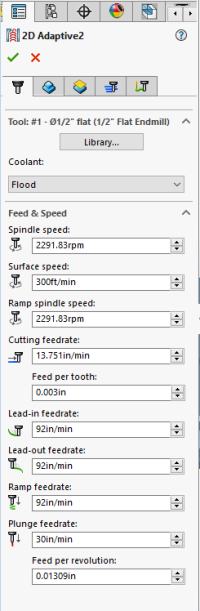
- Tools can be selected from the “all” category of the tool library based on desired tool and modified using the edit button if necessary to set number of flutes and sickout /geometry of tool and tool holder
- Selecting a tool automatically generates generic feeds and speeds for a much more ridged machining center. Feeds and speeds should be set based on the provided chart under references
- Desired machining geometry
- Simply select the desired face or feature to machine in the current operation.Toggling off Z propagation and tangent propagation can be used to select smaller or partial features.
- If this operation is finishing machining a feature based on the previous operation check “rest machining” and input the second tools diameter
- Cutting/retract heights
- Typically selecting machining geometry will set many of the heights automatically, however they can all be altered if necessary
- Machining passes
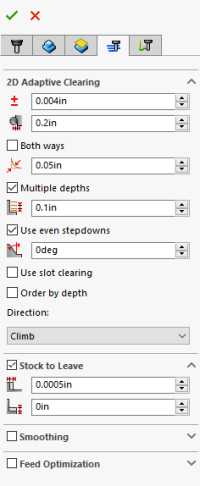
- Part of feeds and speeds, HSM Works will auto fill many of the boxes, however due to the limited power and rigidity of the machine, stepdowns should be reduced based on the reference material and “multiple passes” should be used to reduce cutter load
- “Material to leave” can be adjusted to create roughing passes if desired. Many operations such as adaptive clearing will automatically leave stock as it is assumed to be roughing operations.
- Linking
- Linking moves dictate how the cutter enters and exits the workpiece and can be altered to prevent the cutter from running into the stock while it attempts to start or finish a cut cleanly.
- Simulating
- Any toolpath generated can be previewed using the simulate function built into HSM Works. the Job or single operation can be selected before selecting “simulate” from the Solidworks command bar.
- Simulating code is a great way to see unwanted movements the tool may make or seeing if the tool is undercutting into important areas of the stock or crashing into the workpiece.
- Within simulation “stock” can be triggered on and off to see material removal in real time.
- Posting
- Post the code by selecting Post Process and selecting Carbide 3D (grbl) as the post configuration. The program name or number should be numbers only, and is typically notated 00001 (not necessary for carbide but good practice for larger machines) make sure to select the desired output folder as by default Solidworks buries the G-code


Setting up the Carbide for a Job:
The Carbide router uses fun sized ER11 collets to hold tools from 1 mm to 7 mm but typically uses tools with a 1/8 inch shank.
Changing tools:
- Turn the router off and using an acid brush remove metal shavings and any dust from the tool head
- Using the 17 mm box wrench on the collet nut and the 12 mm open ended wrench on the spindle shaft flats loosen the collet and tool.
- Unscrewing the nut all the way allows the collet and tool to be removed from the spindle and changed out with a different tool of the same shank or with a different sized collet.
- Separating the collet from the collet nut can be done by pushing on the back end of the collet so that it becomes angled within the retaining collet nut and then can be pulled out.
- Before reinstalling the new collet and tool, wipe down the tool shank as well as the collet and spindle tapper.
Homing and Zeroing the machine:
- With the tool installed, make sure the bed is empty and the cover is closed before turning on the machine
- Launch Carbide Motion on the Carbide computer
- Under “Jog” select “Home Machine” and allow machine to home itself
- Select “measure tool” and the machine will use the automatic tool length measuring tool to zero out the tool
- Next while still under “Jog” position the machine can set part zero in three ways
- The less accurate way is to position the tool at part zero established in HSM Works by jogging the machine to the part zero location and pressing zero
- An edge finder can be used at the minimum RPM to find the part X and Y zero. The cutting tool can then be replaced in the spindle and re-zeroed using the automatic tool length touch off. Z zero can be established by sliding a paper of known thickness or a thin metal shim along the top of the part and slowly jogging the spindle down until slight resistance is felt on the shim from the tool tip. X and Y axles must then be adjusted by the radius of the edge finder, and Z Zero must be offset by the shim thickness
- The fastest way to establish part zero is by using the paper or shim on all three axis and offsetting X and Y by the radius of the tool plus shim thickness, and the Z axis by shim thickness.
Starting Job:
- Load the desired G-code using the “Load” page
- Zero out the machine to match part zero
- Start Job
Machine Limitations
- Each tool change should be accompanied by a new job within HSM Works
- Tool shank diameter is limited to 7 mm
- Max stepdown is limited to .01“ in metal and .04” in wood
- Work area is limited to 8“ x 8” x 4“ x,y,z
Choosing tools
Many tools are optimized for different materials, and although a 2 flute endmill can do most operations, it is not always ideal. Single and duel high helix endmills are available for plastics, woods, and composits, with carbide endmills and burs available for abrasive materials such as glass fiber reinforced materials such as circuit boards. Feeds and speeds can be found here
File Types
G-Code files will be posted with the file extension .nc whereas Carbide Create will post files with the file extension .egc. G-code files can be opened directly into a text editor if necessary to preview or edit the desired code. .egc is a propriety package for G-Code used by Carbide for some god forsaken reason, in order to preview the G-code directly it is first necessary to upload the file to Carbide motion before copying and pasting the code into a preferred text editor.
Carbide 3D Quick Review
Tool Lead: Andrew Furst
Contact: Andrewfurst@ucsb.edu
Safety Concerns
- Safety Glasses must be worn when machine is running
- The acrylic shield must be in place and lowered before starting a job
- The spindle must be completely stopped before adjusting or removing work piece
- After milling is completed, the work piece will have developed sharp burrs which must be removed with a hand file or sandpaper
Safe Operating Procedures Review
- Design part using Solidworks or other CAD platform
- Using HSM Works or Carbide Create generate tool paths
- Each different tool needs to be a separate job as only one tool can be loaded into the Carbide at a time
- Use 2D and 3D clearing and pocketing to remove the bulk of the material while using “stock to leave” to allow for a finishing pass
- Simulate the toolpaths to verify that the tool will not crash and is cutting in the desired location
- Using the 17 and 11 mm wrenches loosen the collet nut to change out the tool or collet itself if switching shank diameter
- Home the machine and zero the tool using Carbide Motion under the “jog” heading using paper or a shim. DO NOT FORGET TO ADD OFFSET OF TOOL RADIUS AND SHIM THCINESS
- Upload the G-Code into Carbide Motion under “load”
- Start program
Post Processing
- Use a file to debur the part
Maintenance
- Tools should be wiped clear of chips or coolant using an acid brush
- The router should be vacuumed out after every operation and at the completion of each job
- Once a month the router should be moved and chips cleared from underneath machine body
- Twice a year the router should be partially disassembled, cleaned, and re-oiled